- 您现在的位置:买卖IC网 > Sheet目录39245 > LM-T118SQE2 (AVX CORP) 880 MHz(Tx)-915 MHz(Tx), 925 MHz(Rx)-960 MHz(Rx), DUPLEXER
Antenna Switch Module
Triple-Band LM-T118 Series
Features
Built-in ESD Protection Circuit
Built-in 2Coupling Capacitors and bias
circuit to drive the switch
Built-in 2LPF for Receiver
Small and Low profile
Applications
GSM/DCS/PCS
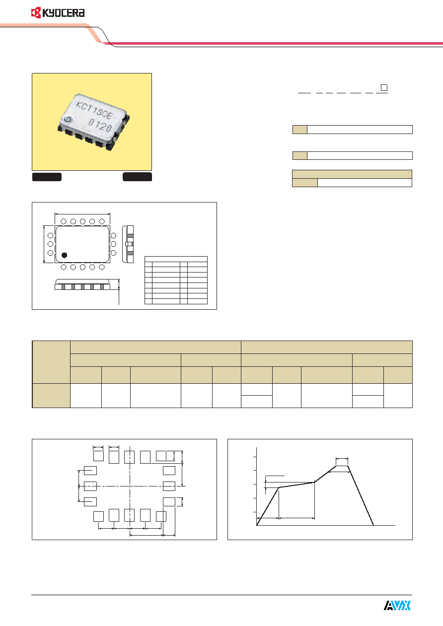
Dimensions
How to Order
LM - T 1 18 SQ E 2
qSeries
wCircuit
eType
rHeight
yESD Function
t, uCustom Specification
qw e r t y u
Recommended Land Pattern
Recommended Reflow Profile
(Unit : mm)
(at 25C)
(Unit : mm)
GND
TX(DCS)/PCS
GND
RX(PCS)
RX(DCS)
RX(GSM)
GND
CONT1
q
w
e
r
t
y
u
i
GND
CONT2
GND
ANT
GND
CONT3
GND
TX(GSM)
o
!0
!1
!2
!3
!4
!5
!6
ESD Protection
E
YES
T
Triple
18
1.8mm max
KC T1SQE
0005
8
7
6
14
15
16
5
4
3
1
2
9
10
11
13
12
5.0
1.8MAX.
6.7
Pin Configuration
GSM
DCS/PCS
TX
RX
TX
RX
Part No.
Freq.
Ins. Loss
Att.(2*f0, 3*f0)
Freq.
Ins. Loss
Freq.
Ins. Loss
Att.(2*f0, 3*f0)
Freq.
Ins. Loss
(MHz)
(dB)
(MHz)
(dB)
(MHz)
(dB)
(MHz)
(dB)
LM-T118SQE2 880 to 915
≤1.3
≥35(2f0), ≥30(3f0) 925 to 960
≤1.3
1710 to 1785
≤1.6
≥28(2f0), ≥30(3f0)
1805 to 1880
1850 to 1910
1930 to 1990
≤1.6
Specifications
Peak:240-250
°C
15sec max
230
°C
over
50sec max
100sec
60sec
250
200
150
100
50
temp.
time
(sec.)
(
°C)
150-190
°C
1.27
1.0
2.7
0.8
1.0
0.7
1.85
Pb Free
RoHS Conforming
发布紧急采购,3分钟左右您将得到回复。
相关PDF资料
LM1036NX
2 CHANNEL(S), TONE CONTROL CIRCUIT, PDSO20
LM103H-3.6
1-OUTPUT TWO TERM VOLTAGE REFERENCE, 3.6 V, MBCY2
LM113GMW8
1-OUTPUT TWO TERM VOLTAGE REFERENCE, 1.22 V, UUC
LM1151
B Type, DOLBY NOISE REDUCTION IC
LM12458MEL/883
PROPRIETARY METHOD ADC, PQCC44
5962-9319501MYA
SPECIALTY ANALOG CIRCUIT, PQCC44
LM12H458MWG-MCP
SPECIALTY ANALOG CIRCUIT, CDFP44
LM12H458MWG/883
SPECIALTY ANALOG CIRCUIT, CDFP44
相关代理商/技术参数
LMT120-3200-35P9-70866TW
制造商:Cree 功能描述:LMR4 12 inch Troffer Module 3200lm
LMT120-3800-35P9-70866TW
制造商:Cree 功能描述:LMR4 12 inch Troffer Module 3800lm
LMT1-XXX-5
制造商:RADIOMETRIX 制造商全称:RADIOMETRIX 功能描述:VHF Narrow Band FM Low Cost multi channel radio modules
LMT2
制造商:RADIOMETRIX 制造商全称:RADIOMETRIX 功能描述:UHF Narrow Band FM Low Cost multi channel radio modules
LMT2-433-10
制造商:RADIOMETRIX 制造商全称:RADIOMETRIX 功能描述:UHF Narrow Band FM Low Cost multi channel radio modules
LMT2-433-5
制造商:RADIOMETRIX 功能描述:TRANSMITTER 433.90-434.65MHZ
LMT2-433-5-12K5
制造商:RADIOMETRIX 制造商全称:RADIOMETRIX 功能描述:UHF Narrow Band FM Low Cost multi channel radio modules
LMT2-458-10
制造商:RADIOMETRIX 制造商全称:RADIOMETRIX 功能描述:UHF Narrow Band FM Low Cost multi channel radio modules